Posted on

7 Ways to Speed Up Structural Steel Drafting in AutoCAD

Structural steel detailing in AutoCAD can feel slow when you’re constantly redrawing shapes, trimming geometry, fixing layers, or hunting for old profiles. These small inefficiencies add up quickly — especially on framing plans, shop drawings, and connection details .

If you want cleaner drawings, fewer errors, and a faster workflow, these seven improvements will make an immediate difference.

Complete Steel Detailing Tools for AutoCAD

Faster AutoCAD text workflows with QuickNotes

1. Standardize Your Steel Profiles Early

One of the biggest time losses in steel detailing comes from redrawing shapes or searching for old geometry. A consistent library of W‑shapes, channels, angles, and HSS profiles ensures every shape matches published dimensions and prevents mismatched or outdated geometry .

Why it speeds you up:

  • No more redrawing

  • No more guessing dimensions

  • Faster design changes


2. Use Pre‑Sized Shapes Instead of Drawing Profiles Manually

Manual drafting requires offsets, fillets, trimming, and scaling — all repetitive steps that slow down beams, columns, bracing, and section views .

Using pre‑sized shapes eliminates those steps entirely and ensures the geometry is always correct .

Why it speeds you up:

  • Zero trimming

  • Zero scaling

  • Zero cleanup

3. Insert Shapes in the Correct View (Plan, Section, Elevation)

Switching between views and redrawing profiles is a hidden time sink. A better workflow is to choose the shape, choose the view, and place it directly where it belongs — reducing trimming and rotation work .

Why it speeds you up:

  • No rotating profiles

  • No redrawing for each view

  • Cleaner geometry from the start

Steel Shapes in Elevation View

4. Keep Steel Shapes on the Correct Layers Automatically

Fixing layer mistakes is one of the most common cleanup tasks. A good workflow ensures beams, columns, hidden lines, and centerlines always land on the correct layers, keeping drawings consistent across the project .

Why it speeds you up:

  • No layer cleanup

  • No reassigning objects

  • Consistent standards across drawings

5. Use Repeatable Workflows for Shop Drawings

Shop drawings benefit from predictable steps: insert shape, add dimensions, add connection details, add callouts. When the geometry is already correct, the rest of the detailing process becomes much faster .

Why it speeds you up:

  • Less rework

  • Faster dimensioning

  • Cleaner detail sheets

6. Reduce Repetitive Tasks Wherever Possible

Steel detailing includes many repetitive actions — drawing the same shapes, copying geometry, fixing inconsistencies, adjusting text and dimensions. Removing repetition dramatically improves drafting speed .

Why it speeds you up:

  • Fewer clicks

  • Fewer corrections

  • More time for actual detailing

7. Keep Your Steel Shape Library Updated

Standards change. Projects vary. Teams evolve. Keeping your library current prevents outdated dimensions, mismatched profiles, and manual corrections later .

Why it speeds you up:

  • No outdated geometry

  • No manual fixes

  • Consistent accuracy across projects

Final Thoughts

Improving your structural steel workflow comes down to a few core principles: use accurate ready‑to‑place shapes, reduce manual drafting steps, keep geometry consistent, automate repetitive tasks, and maintain a clean library. These changes save hours on every project and reduce errors across your drawing.

Improve your steel detailing productivity

Posted on

MText vs QuickNotes: Faster AutoCAD Text Placement Workflows

Introduction

AutoCAD users often spend large amounts of time repeatedly typing notes, copying MText objects between drawings, and editing repetitive annotations. While AutoCAD MText provides powerful formatting capabilities, repetitive note placement can slow down drafting workflows significantly.

QuickNotes provides an alternative workflow that allows users to quickly select and place reusable notes directly into AutoCAD drawings.

In this article, we compare traditional AutoCAD text workflows with QuickNotes productivity workflows.


 Why Repetitive AutoCAD Text Placement Becomes Slow

For many AutoCAD users, text placement and annotation become one of the most repetitive parts of the drafting process. While drawing geometry often receives most of the attention, repetitive text editing, note placement, and annotation management can quietly consume a large amount of production time throughout a project.

In many drafting environments, users repeatedly:

  • type the same notes over and over
  • copy and paste text from older drawings
  • search through previous projects for commonly used notes
  • edit similar annotations multiple times
  • recreate standard notes for each sheet or detail

These workflows may seem minor individually, but across dozens or hundreds of drawings, the time loss becomes significant.

Traditional AutoCAD text workflows using MText or standard text commands work well for creating detailed annotations and formatted specifications. However, repetitive note placement often becomes inefficient when users continually reuse the same text throughout multiple drawings.

For example, structural steel detailers frequently place repetitive fabrication and erection notes across numerous shop drawings. Architectural drafters often reuse standard project notes, while mechanical drafting workflows commonly rely on repeated manufacturing or installation annotations. In many cases, the same text content is recreated countless times during a project lifecycle.

Another common issue is note consistency. When text is manually retyped or copied between drawings, small variations can appear:

  • spelling differences
  • inconsistent wording
  • outdated revisions
  • formatting inconsistencies
  • missing information

Over time, these inconsistencies can create confusion across project documents and increase the amount of manual checking required before final delivery.

Copy-and-paste workflows can also become difficult to manage. Many users maintain “master drawings” or old project files simply to retrieve previously used notes. Searching through older drawings for commonly used annotations interrupts drafting flow and adds unnecessary steps to routine tasks.

As projects become larger and deadlines become tighter, repetitive annotation work can become a hidden productivity bottleneck inside AutoCAD workflows.

This is where reusable note systems and organized annotation libraries can significantly improve drafting efficiency. Instead of repeatedly typing or searching for notes, users can quickly select standardized annotations and place them directly into drawings, reducing repetitive work and helping maintain consistency throughout projects.

Where AutoCAD MText Works Well

AutoCAD MText remains one of the most powerful and flexible text tools available for drafting and design workflows. For many applications, MText is the ideal solution because it provides advanced formatting controls and allows users to create detailed, professional-looking annotations directly within AutoCAD drawings.

MText is especially effective when working with:

  • large blocks of descriptive text
  • specifications and project notes
  • formatted paragraphs
  • multi-line annotations
  • tabulated information
  • detailed instructions
  • revision notes
  • title block information

One of the major advantages of MText is its formatting capability. Users can apply:

  • multiple text styles
  • varying text heights
  • bold and italic formatting
  • columns and paragraph spacing
  • bullets and numbered lists
  • special symbols and characters
  • stacked fractions and tolerances

This level of formatting makes MText extremely useful for documentation-heavy drawings where readability and presentation are important.

MText also provides strong editing flexibility. Users can quickly modify large sections of text without recreating individual text objects. For drawings that contain lengthy notes or specifications, this can be far more efficient than managing multiple single-line text entities.

Another advantage is compatibility with standard AutoCAD drafting workflows. Because MText is built directly into AutoCAD, it integrates naturally with:

  • annotation scaling
  • dimension styles
  • text styles
  • plotting workflows
  • sheet layouts
  • external references
  • standards management

For many drafting situations, MText is absolutely the correct tool to use.

However, challenges begin to appear when users repeatedly place the same notes throughout multiple drawings or projects. Tasks such as:

  • placing standard fabrication notes
  • inserting repetitive installation instructions
  • reusing general project notes
  • copying standard disclaimers
  • recreating frequently used annotations

can become repetitive and time-consuming when performed entirely through traditional MText workflows.

In these situations, the issue is not with MText itself, but with the repetitive nature of the workflow. Repeated typing, searching old drawings for previous notes, or copying and pasting annotations between sheets can slow production and interrupt drafting efficiency.

This is where productivity-focused tools such as QuickNotes can complement traditional AutoCAD text workflows. Instead of replacing MText, QuickNotes helps streamline repetitive annotation tasks by allowing users to quickly access and place reusable notes while still maintaining compatibility with standard AutoCAD drafting practices.

How QuickNotes Improves AutoCAD Annotation Productivity

QuickNotes is designed to simplify repetitive text placement workflows inside AutoCAD by allowing users to quickly access and place reusable notes directly into drawings.

Instead of repeatedly typing the same information or searching through previous projects for existing annotations, users can organize commonly used notes into reusable libraries for faster access.

This workflow can help improve:

  • drafting speed
  • annotation consistency
  • note organization
  • repetitive workflow efficiency
  • project standardization

QuickNotes is especially useful in environments where the same annotations are repeatedly used throughout multiple sheets, details, or projects.

Users can quickly:

  1. organize standard notes
  2. select notes from categorized lists
  3. place notes directly into drawings

This approach reduces repetitive typing while helping maintain consistency across project documentation.

Because QuickNotes works alongside AutoCAD workflows, users can continue using traditional MText where advanced formatting is required while streamlining repetitive annotation tasks through reusable note placement.

MText vs QuickNotes Comparison Table


Traditional MText Workflow QuickNotes Workflow
Repeated typing Reusable note placement
Copy/paste between drawings Organized note libraries
Searching old drawings for notes Quick categorized access
Manual note recreation Faster repetitive workflows
Inconsistent wording Standardized annotations
Repetitive editing Streamlined note placement

Quick Notes App

Posted on

AutoCAD Wipeout Command: Try It Now!

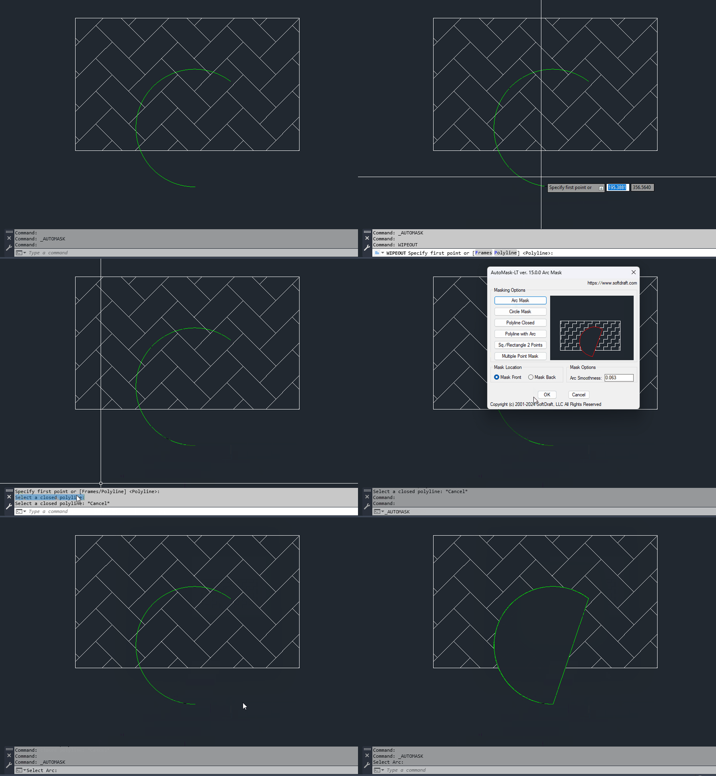
Are you new to the AutoCAD Wipeout command and feeling overwhelmed by all the command options and how to use them? Fear not! This blog post will guide you through the essential AutoCAD wipeout command, a handy tool for keeping your drawings clean and clutter-free. If you need to add wipeouts to arcs, circles, polylines with arcs, or non-closed polylines, check out the AutoMask Wipeout App at the bottom of this post.

What is a Wipeout?
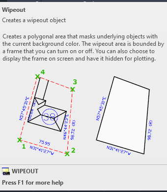
Imagine you’re working on a detailed architectural drawing. Unnecessary elements like dimensions, text annotations, or unwanted geometry might distract from the main design. A wipeout acts like a digital eraser, masking these elements with the current background color, essentially hiding them from view.

Getting Started with Wipeout:

There are two main ways to access the wipeout command:

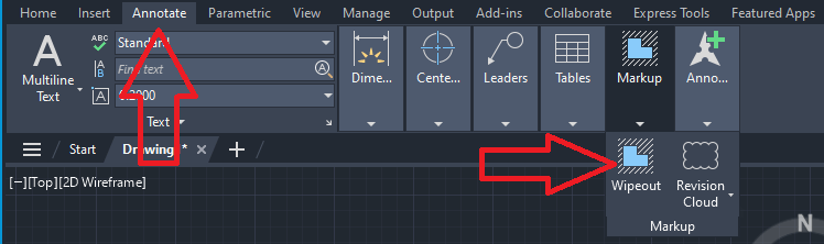
  • Ribbon Menu: Locate the “Annotate” tab on the ribbon. In the “Markup” panel, you’ll find the “Wipeout” button.
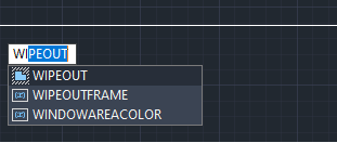
  • Command Line: Alternatively, type “WI” (the short alias for wipeout) into the command line at the bottom of your AutoCAD window and press Enter.

Creating a Wipeout:

Once you’ve initiated the wipeout command, AutoCAD will prompt you to specify points.

Command: WIPEOUT
Specify first point or [Frames/Polyline] :

Click around the perimeter of the area you want to hide, following your desired shape. Each click defines a corner point of the wipeout boundary. Double-click or press Enter to finalize the shape.

Understanding Wipeout Options:

While creating a wipeout, you will see the options [Frames/Polyline]. Frames are essentially the outline of the wipeout boundary. We will discuss the Polyline option in an upcoming post. Here’s a breakdown of your options:

  • On: This makes the frame visible, clearly distinguishing the hidden area from the rest of the drawing.
  • Off: The frame disappears, leaving only the hidden area visible. This can provide a cleaner look.

Editing Wipeouts:

Just like any other AutoCAD object, wipeouts can be edited after creation. Select the wipeout, and grips will appear at each corner point. Drag these grips to modify the shape. You can also use the “Properties” palette to adjust the fill color or assign the wipeout to a specific layer for better organization.

Wipeouts: Your Drawing’s Best Friend:

Mastering the wipeout command is a valuable skill for any AutoCAD user. It helps you present clear, concise drawings by hiding unnecessary clutter. So, the next time your drawing feels overloaded, remember the wipeout – a simple tool that significantly impacts your design communication.

Wipeout has a lot more to offer, so stay tuned for the next post.

Posted on

StoreFront2D Added To App Store

SoftDraft’s StoreFront2D has been added to AutoCAD Mechanical_English as Featured Apps.
Autodesk App Store Team.

If you draw storefronts in plan or elevation views, then this app will definitely save you lots of time. This is a command line driven app that allows you to add a continuous string of storefront single / double doors or windows just by typing the dimensions.

Dimensions are placed on the layer “DIM” and the StoreFront lines are placed on the current layer.

StoreFront App – Software Plugins For CAD – Product (softdraft.com)

StoreFront 2D

Posted on

Carbon Steel Buttweld Fittings 2D App Try Now!

buttweld pipe fittings 2D

Carbon Steel Buttweld Fittings 2D App has been added to AutoCAD_English Exchange Store as Featured New Apps.

The SoftDraft CSBW-2D App, also known as the Carbon Steel Buttweld Fittings 2D Imperial App, is a tool designed to revolutionize the way you create 2D piping drawings.

Pipe Spool Feature: This unique feature allows you to draw a pipe spool with two selection points and selected start and end fittings. This feature alone can save many hours of pipe drawing time.

Posted on

Base Mounted Pumps 2D Now Available!

Base Mounted End Suction Pumps

BMESP 2D now available in the AutoCAD Exchange Store and on the SoftDraft website.

With the BMESP 2D App, you’re equipped to design various 2D end suction pumps tailored to your needs by plugging in different manufacturers’ dimensions. You just need to input the specific dimensions for each pump. With BMESP 2D, you can save your pump measurements for later and pull up the specs in another drawing when you need them.

Base Mounted End Suction Pumps 2D‘s versatility shines through by letting you position the discharge on the left, dead center, or at the far end to suit varied setup needs. The app also caters to a broad selection of suction and discharge sizes, from 1/2″ to 42″. Besides its versatility in handling suction and discharge sizes ranging from 1/2″ to a massive 42″, the app also packs a variety of flange ratings, perfect for crafting precise 3D models of end suction pumps with ease.

Posted on

Pumps 3D App

Pumps 3D App

Pumps 3D App has been added to AutoCAD_English Exchange Store as Featured Paid Apps.

The Pumps 3D application is a comprehensive digital tool that seamlessly integrates three distinct pump types—Base Mounted End Suction, Horizontal Split Case, and Vertical In-Line—into a singular, user-friendly platform. For those with more specialized needs, there’s also the option to acquire individual apps tailored for each specific pump model.

Pumps 3D

Posted on

QuickBrick App: The Best Solution For Brick Coursing In AutoCAD

Brick Coursing App for AutoCAD

QuickBrick App is now available in the AutoCAD Exchange Store and on the SoftDraft website.

Brick Coursing for Wall Sections

QuickBrick is for creating brick coursing using a variety of brick types, joint selections and wall thicknesses. Five different brick types include Standard, Engineer, Economy, Norman and Utility. Seven different joint types include None, Struck, Concave, Flush, Weathered, V-Shaped, and Raked.

QuickBrick™ Includes:

  • Brick types include Standard, Engineer, Economy, Norman and Utility
  • User Specified Air-Space Cavity
  • User Selected Layers for Brick, Brick Hatch, and Joint Hatch
  • Various Joint Types Include None, Struck, Concave, Flush, Weathered, V-Shaped, and Raked
  • Different Joint Types may be set for the Left and Right side of the Brick
  • Brick Start Options include Full Joint, Half Joint or Brick
  • Brick End Options include Joint or Brick
Posted on

CMU Factory App Try It Now!

Architects, builders, and designers can create Concrete Masonry Units (CMU) blocks in Plan view with the help of CMU Factory, a robust software program. Users can design unique and customized CMU blocks to match their specific project demands with this application’s wide range of options for each end condition and face condition.

CMU Factory’s ability to offer several preset selections for various concrete masonry unit sizes is one of its primary strengths, giving customers a multitude of possibilities to choose from to meet their project requirements. Additionally, the application gives users the freedom to add additional options to these preset settings, giving them the ability to construct a fully customized set of block sizes and configurations.

Users can quickly and simply create accurate, to-scale drawings of their concrete masonry units with CMU Factory. Users may easily change and refine designs in real time with the application’s user-friendly features and intuitive interface. This allows users to experiment with alternative configurations until they get the ideal outcome.

In conclusion, CMU Factory is a vital resource for anyone tasked with designing blueprints for the positioning of CMU blocks. Its extensive feature set, pre-made choices, and adaptability make it a highly effective and versatile software tool that can help users save time and effort during the design process.

CMU Size and Placement Options:

  • Width Options: 2″/3″/4″/6″/8″/10″/12″/16″
  • Height Options: 4″/5″/8″/12″/16″
  • Length Options: 4″/8″/12″/16″/24″
  • Placement Options: Lower Left/Lower Right/Top Left/Top Right
  • Layer Selection from Layer List


CMU Hatch Pattern Options:

  • Hatch Pattern
  • Hatch Scale
  • Hatch Angle
  • Hatch Layer Selection from Layer List


CMU Core/End/Face Options:

  • Core Options:Solid/1 Core/2 Cores/3 Cores
  • Left End Options: Stretcher/Corner/Corner Sash/single Bullnose/Double Bullnose
  • Right End Options: Stretcher/Corner/Corner Sash/single Bullnose/Double Bullnose
  • Face Finish Options: Smooth/Split
  • Face Options: 1-7 Score/2-8 Ribs


CMU Joint Options:

  • Joint Type:
  • Joint Layer Selection from Layer List
  • Add Left End Joint Toggle
  • Add Right End Joint Toggle


Restore from List of Saved CMU Presets

Save CMU Selections to Restore List for Faster Selection.